Once you have installed the Arduino IDE, open it up and click on preferences.
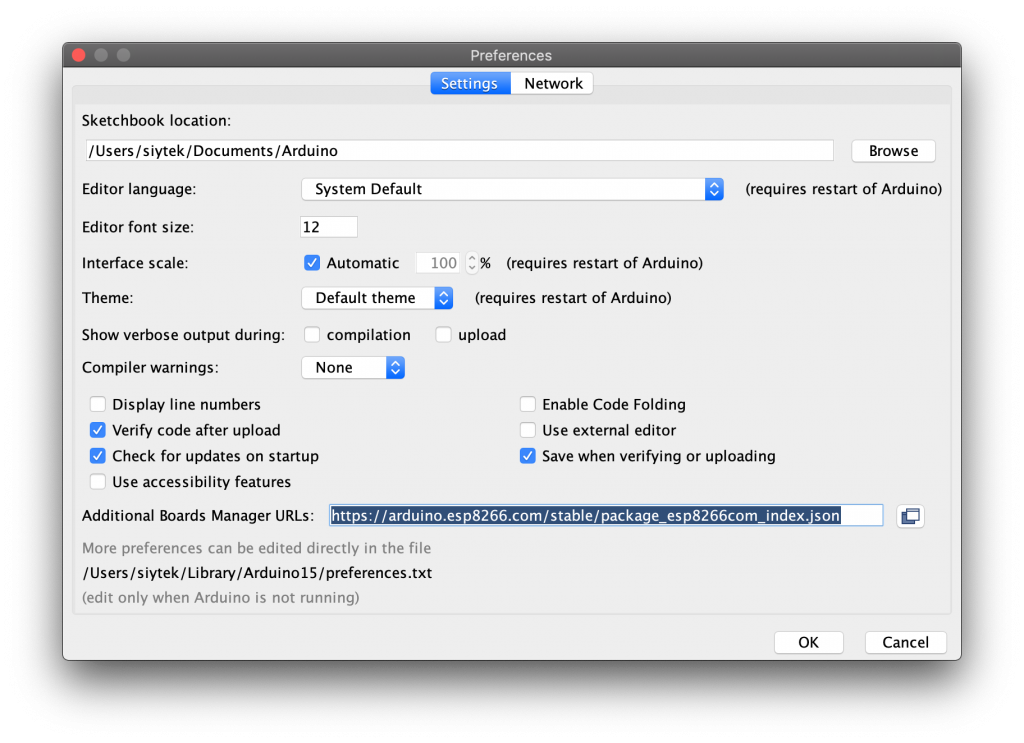
We will need to add the ESP board manager URL. Enter the following into the additional board manager URLs text box.
https://arduino.esp8266.com/stable/package_esp8266com_index.json
If you need to use multiple board managers, you can click the small icon to the right of the text box and enter multiple URLs.